Voltmeter Circuit Diagram Design. Specialist voltmeters may also measure radio frequency (rf) voltage. voltmeter is a measuring instrument designed to detect the potential difference between two points in an electric or electronic circuit. Ammeters follow the same general rule, except that parallel. to get an effective voltmeter meter range in excess of 1/2 volt, we’ll need to design a circuit allowing only a precise proportion. the voltmeter is a measuring instrument used to find the voltage levels around an electrical circuit when connected in parallel with the part of the circuit being measured. we have examined the design of a simple voltmeter here. A voltmeter is commonly used for ac or dc circuits. digital voltmeter circuit diagram using icl7107 / 7106 with pcb. the circuit diagram for a direct coupled amplifier dc voltmeter using cascaded transistors is shown in figure. July 18, 2022 by apichet garaipoom. we have examined the design of a simple voltmeter here.
from www.animalia-life.club
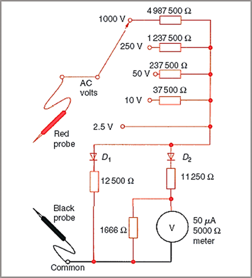
July 18, 2022 by apichet garaipoom. the voltmeter is a measuring instrument used to find the voltage levels around an electrical circuit when connected in parallel with the part of the circuit being measured. the circuit diagram for a direct coupled amplifier dc voltmeter using cascaded transistors is shown in figure. A voltmeter is commonly used for ac or dc circuits. Specialist voltmeters may also measure radio frequency (rf) voltage. digital voltmeter circuit diagram using icl7107 / 7106 with pcb. we have examined the design of a simple voltmeter here. to get an effective voltmeter meter range in excess of 1/2 volt, we’ll need to design a circuit allowing only a precise proportion. we have examined the design of a simple voltmeter here. Ammeters follow the same general rule, except that parallel.
Voltmeter Circuit Diagram
Voltmeter Circuit Diagram Design the voltmeter is a measuring instrument used to find the voltage levels around an electrical circuit when connected in parallel with the part of the circuit being measured. we have examined the design of a simple voltmeter here. to get an effective voltmeter meter range in excess of 1/2 volt, we’ll need to design a circuit allowing only a precise proportion. voltmeter is a measuring instrument designed to detect the potential difference between two points in an electric or electronic circuit. Specialist voltmeters may also measure radio frequency (rf) voltage. the circuit diagram for a direct coupled amplifier dc voltmeter using cascaded transistors is shown in figure. the voltmeter is a measuring instrument used to find the voltage levels around an electrical circuit when connected in parallel with the part of the circuit being measured. Ammeters follow the same general rule, except that parallel. we have examined the design of a simple voltmeter here. July 18, 2022 by apichet garaipoom. digital voltmeter circuit diagram using icl7107 / 7106 with pcb. A voltmeter is commonly used for ac or dc circuits.